Facility managers and plant engineers are reaching the same conclusion: the conventional cooling tower drive train — motor, coupling, long shaft, bevel gearbox — is not just a maintenance burden, it is a continuous, compounding energy tax. This article explains the engineering behind direct-drive permanent magnet cooling tower motors, presents documented efficiency and cost data, and answers the practical questions engineers ask before making the switch.
1. The drive-train problem nobody talks about
A conventional cooling tower drive system looks like this: a TEFC induction motor connects via coupling to a long horizontal shaft, which feeds a right-angle bevel gearbox, which finally drives the fan. It works. It is also, by design, a chain of energy-consuming failure points.
Cooling tower gearboxes operate in one of the harshest environments in industrial settings — saturated air, constant vibration, wide temperature swings, water mist. Gearbox oil must be sampled and replaced on a schedule. Shaft alignment drifts over time, accelerating bearing and seal wear. Couplings degrade. Every mechanical interface adds friction loss.
Maintenance costs add to the picture. Gearbox oil sampling and changes, shaft alignment checks, coupling inspections, and the labor for each — these are budgeted costs that look normal because they have always been there. They are not inevitable.
2. How direct-drive permanent magnet motors work differently
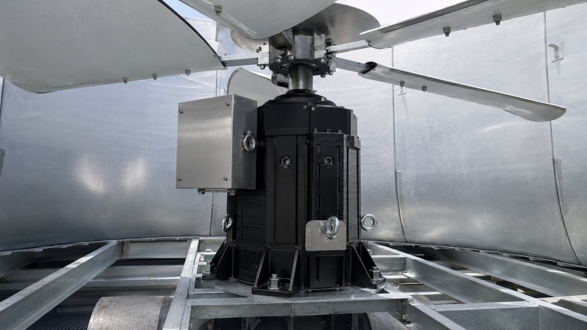
A direct-drive permanent magnet (PM) synchronous motor connects the motor rotor directly to the cooling tower fan shaft. No gearbox. No long shaft. No coupling. No oil. The motor runs at the fan's natural low speed — typically 150 to 250 rpm — using a high pole count (66 or 88 poles in the SQMC series) to develop torque at speed without a gear ratio.
Permanent magnets in the rotor produce a strong magnetic flux field with no excitation current — meaning no rotor copper losses. Speed is precisely controlled by changing frequency through a standard VFD (variable frequency drive). Sensorless flux vector control is supported, eliminating the need for an encoder in most applications.
3. Efficiency in the real world: what the numbers mean
Motor efficiency classes — IE3 (Premium Efficiency) and IE4 (Super Premium Efficiency) — are measured at the motor shaft. They do not account for what is between the motor and the load. If your drive train includes a gearbox, the nameplate efficiency is meaningless for actual system efficiency.
Direct drive eliminates the gearbox from the equation. Motor shaft torque is fan torque. What the nameplate says is what the fan sees.
The SQMC series delivers the following nominal efficiencies across its model range:
| Motor Model | Poles | Power (kW) | Speed (rpm) | Torque (Nm) | Efficiency |
|---|---|---|---|---|---|
| SQMC132-150 | 66 | 6.5 | 200 | 310 | 94.5% |
| SQMC132-200 | 66 | 8.4 | 200 | 400 | 95.0% |
| SQMC132-250 | 66 | 10.5 | 200 | 500 | 95.5% |
| SQMC200-300 | 88 | 23.0 | 200 | 1,100 | 93.5% |
| SQMC250-500 | 88 | 58.6 | 200 | 2,800 | 95.0% |
These numbers are at rated load. The advantage of PM motors over induction motors is that efficiency stays high across a wide range of speed and torque, not just at one optimum operating point. For cooling towers that modulate fan speed seasonally or by load, this is particularly valuable.
4. Field case study: 33% measured energy reduction
The most reliable efficiency argument is not a datasheet — it is a measurement. The data below comes from a direct retrofit installation where a conventional gearbox-driven fan system was replaced with an EMF Motor SQMC direct-drive unit, with before-and-after power consumption logged under matched airflow and fan-speed conditions.
Field measurement results — same airflow, same fan speed
Before-and-after power measurement under identical operating conditions.
That level of saving — 33% on the same performance output — is at the upper end of what direct-drive retrofits typically achieve. The 15–25% range is the more conservative, broadly repeatable expectation across mixed installation conditions and load profiles. What the case study shows is that the ceiling is meaningfully higher when the gearbox being replaced is aged or operating below optimum.
5. 5-year savings projections by power rating
The estimates below assume $0.12/kWh, continuous duty at rated load, and a 15–25% efficiency improvement vs the conventional gearbox-driven system. Maintenance savings (gearbox oil, labor, shaft alignment, unplanned downtime) are excluded — actual total savings will be higher.
| Motor Power | Annual Savings (15%) | Annual Savings (25%) | 5-Year Savings (mid) |
|---|---|---|---|
| 45 kW | $4,236 | $7,060 | $28,240 |
| 55 kW | $5,178 | $8,630 | $34,520 |
| 75 kW | $7,060 | $11,765 | $47,060 |
For sites with multiple cooling tower cells, fleet-wide retrofit economics become significant quickly. A 10-cell installation with 55 kW fans can mean over $340,000 of energy savings across five years, before maintenance reductions are added.
6. Technical specifications: SQMC series
The SQMC series is engineered specifically for the cooling tower environment — outdoor mounting, continuous duty, in-airflow operation, and aggressive ambient conditions.
ISO 12944-2 C5VH is the highest corrosion category, covering offshore, coastal, and severely aggressive industrial environments. Offered as an option on the SQMC series, it means the motor enclosure, fasteners, and surface treatments are specified for long service life in the wet, chemically active atmosphere of a cooling tower plenum.
7. Engineer FAQ
Will this motor work with our existing VFD?
In most cases, yes. SQMC motors support sensorless flux vector control, which is available on virtually all modern industrial VFDs. For applications requiring tighter speed regulation, a simple encoder can be added. The EMF Motor engineering team provides VFD compatibility guidance as part of the application review.
What happens to the shaft hole in the fan deck?
Eliminating the long shaft means the fan deck hole penetration can be sealed. This reduces air bypass around the fan and improves volumetric efficiency — a secondary gain that often improves measured airflow at the same fan rpm.
How does this fit into predictive maintenance programs?
Direct-drive motors have fewer failure modes than gearbox systems, which simplifies condition monitoring. Vibration signature is cleaner because there is no gearbox harmonic to filter out. Optional PT100 winding temperature sensors and vibration sensors can be specified at order — supporting integration with existing PLC or SCADA-based predictive maintenance platforms.
What is the retrofit installation process?
The SQMC motor mounts directly to the fan hub via a standard flange or foot mount. Removing the existing gearbox, shaft, and couplings is straightforward. Because there is no shaft alignment to perform, commissioning time is significantly shorter than replacing a conventional drive train. EMF Motor provides dimensional drawings for pre-installation planning.
Is this motor certified?
The SQMC series is CE-certified. For specific regional certifications (UL, CSA, EAC, etc.), contact the EMF Motor engineering team to discuss your application requirements and timeline.
Ready to evaluate direct drive on your cooling towers?
The EMF Motor engineering team will review your existing motor data, fan specifications, and operating profile — and provide a site-specific energy savings estimate at no cost.
Request Engineering Review →